+86 139 2233 0292

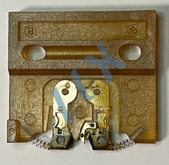
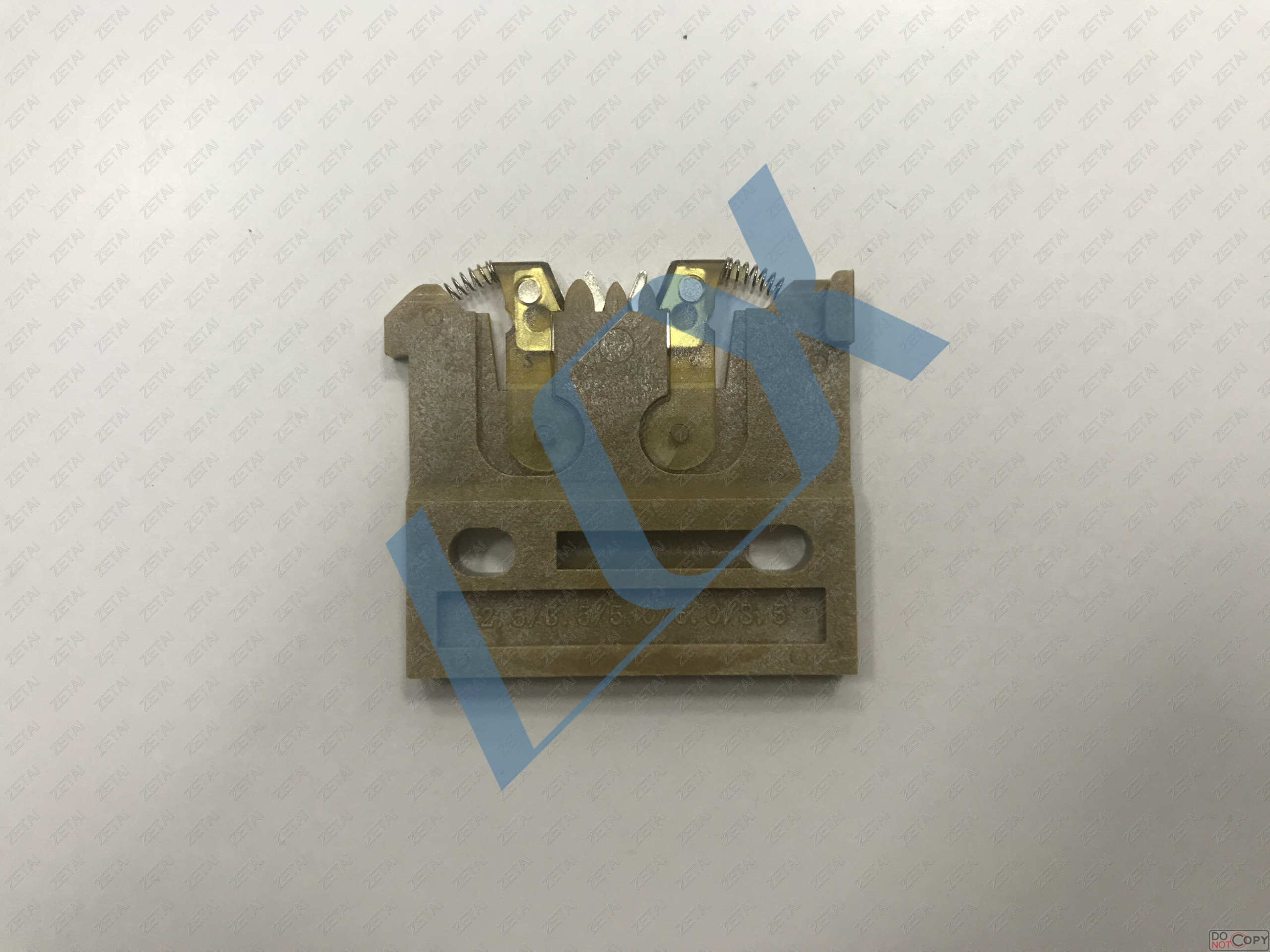
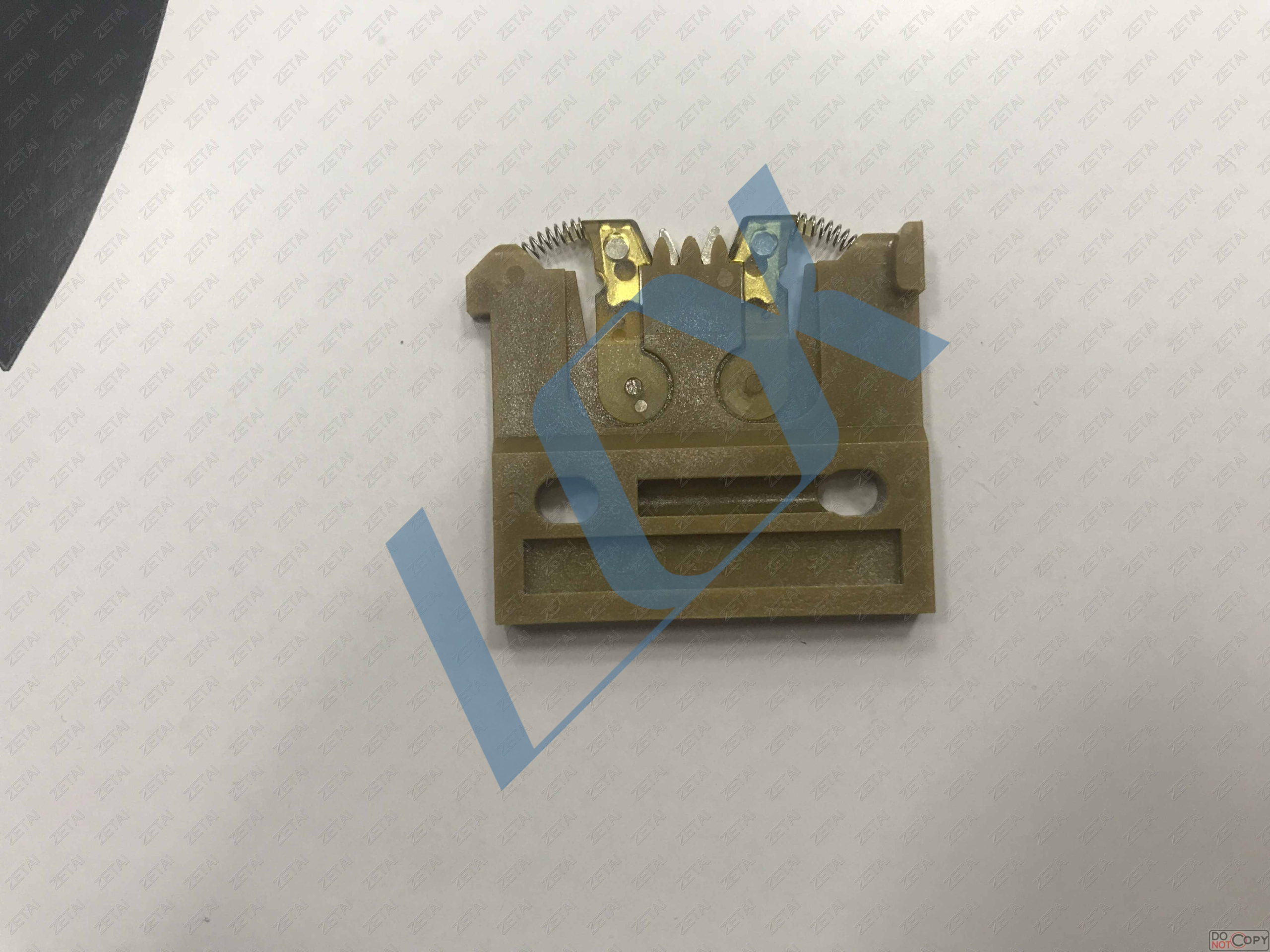
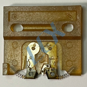
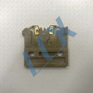
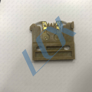
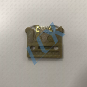
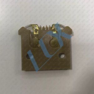
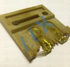
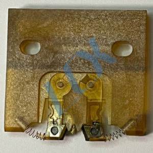
Universal UIC 52556101 (2.5 5.0 7.5) Bracket Clip Assembly .AI Spare Parts Bracket clip assembly, dual span (2.5/5.0/7.5/10.0) 52570301 52556002 52556101 52532001 52532002 42804703, 42804704, 42804703X 48820001, 90055421 90054812
Universal UIC 2.5 5.0 7.5 10.0 Bracket Clip 52532002 .AI Spare Parts
52570301 Bracket clamp assembly, double span (2.5/5.0)
52556001 Small three-span bracket clamp assembly (2.5/5.0/7.5)
52556002 3.5 three-span bracket clamp assembly (2.5/5.0/3.5)
52556101 Large three-span bracket clamp assembly (5.0/7.5/10.0)
52532001 Four-span bracket clamp assembly (2.5/5.0/7.5/10.0)
52532002 Four-span bracket clamp assembly (2.5/5.0/7.5/10.0)
48797303 Printed circuit board; CPU 51
46088103 Printed circuit board; UIMC 3
46088101 Axis controller; UIMC
Share to:
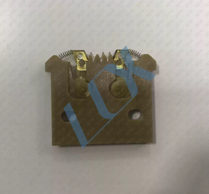
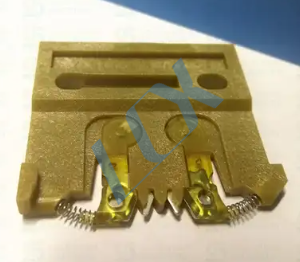
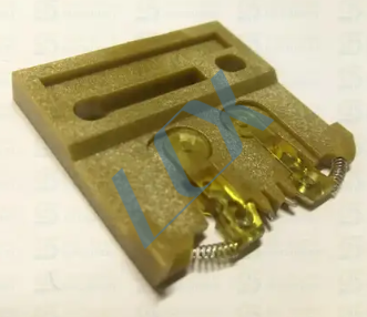
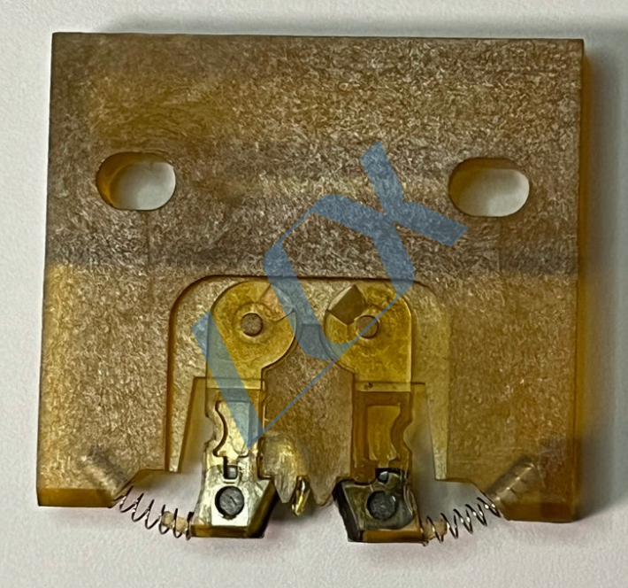
52532001 Carrier Clip (Universal Instruments AI Insertion Machine Chain Clip)
🔍 Basic Product Information
Model: 52532001 (also commonly known as Carrier Clip Assembly)
Brand: Universal Instruments (UIC)
Applicable Equipment: AI (Automatic Insertion Machine) series equipment, also compatible with domestic vertical insertion machines such as Xinzegu and Zhonghexu
Core Function: In the material conveyor system of the insertion machine, it is used to fix and pull the carrier tape of components, ensuring stable material feeding, preventing material jumping and deviation, and ensuring insertion accuracy.
📐 Specifications and Structural Details
Compatible Span: Supports Quad Span (2.5mm / 5.0mm / 7.5mm / 10.0mm), corresponding to carrier tapes with different component pin pitches.
Main Material: High-temperature resistant engineering plastic (glass fiber reinforced PPS/PEEK type), wear-resistant and deformation-resistant, suitable for the high-temperature, high-frequency working environment of insertion machines.
Key Components:
Gold metal grippers (with spring return structure): Responsible for clamping the edge of the carrier tape for precise feeding.
Center positioning teeth: Engage with the carrier tape positioning holes to ensure accurate feeding step distance.
Mounting Holes: Used for fixing to the insertion machine’s rack/station mechanism.
Double-sided Structure:
Front Side: With specification markings (such as corresponding span size) for quick model identification.
Back Side: Flat mounting surface for secure mounting to the equipment.
⚙️ Working Principle and Application Scenarios
Workflow: After the carrier tape is fed from the tray, it is clamped by the metal claws of the chain clamp. In conjunction with the equipment drive mechanism, it is conveyed forward at set intervals, precisely delivering the components below the insertion head to complete the insertion process.
Typical Applications: Automated insertion process for through-hole components (resistors, capacitors, connectors, etc.)
High-speed insertion machine conveyor system, solving carrier belt slippage and skipping issues
Compatible production of multi-specification components, adapting to different materials by changing chain clamps of different spans
⚠️ Maintenance and Replacement Points
Wear Inspection:
Fatigue and insufficient elasticity of metal gripper springs can cause the carrier belt to slip and not grip tightly.
Wear of positioning teeth can cause feed pitch deviation, resulting in insertion misalignment.
Cracks/deformation of the plastic body can affect installation accuracy and service life.
Replacement Recommendations:
Regularly check the gripper elasticity and positioning tooth wear. Replacement is recommended if the following conditions are observed:
Inserted insertion misalignment or significantly increased skipping frequency
Unstable carrier belt feed, requiring frequent adjustments to the feed rack
Cracks, severe wear, or broken springs in the chain clamps
Installation Precautions:
Align the chain clamp with the carrier belt guide during installation to avoid gripper misalignment causing carrier belt jamming.
The mounting holes must be firmly fixed to prevent loosening and displacement during operation.
📌 Additional Notes
This model is compatible with Universal Instruments… Chain clips such as 52570301 and 42804703 are components with the same function but different specifications. The main difference is that they are compatible with different carrier belt spans. When replacing them, the corresponding model should be selected according to the pin spacing of the production material.
Below is a complete comparison table of chain clamp models, compatible specifications, and applicable scenarios for different spans within the same series, to facilitate your quick selection:
Model Compatible Span (Step Pitch) Compatible Device Type Typical Application Scenarios
52532001 Quad Span: 2.5 / 5.0 / 7.5 / 10.0 mm Multi-specification universal AI insertion machine For multi-pin pitch components such as resistors, capacitors, and connectors
52570301 Dual Span: 2.5 / 5.0 mm Dedicated insertion machine for radial components Small pitch radial components (such as diodes and capacitors)
42804703 Single Span: 2.5 mm Narrow band dedicated rack 2.5mm standard carrier tape components
42804704 Single Span: 5.0 mm Narrow band dedicated rack 5.0mm standard carrier tape components
48820002 Triple Span: 5.0 / 7.5 / 10.0 mm Dedicated for wide pitch components High pin count connectors, pin headers, and other large-pitch components
🔍 Key Selection Guidelines
Span Definition: Refers to the center distance between the chain clamp positioning teeth and the carrier tape hole, directly corresponding to the component pin pitch. Incorrect selection will lead to feed pitch deviation and component misalignment.
General vs. Special Purpose:
Your current 52532001 (Quad Span) is a general purpose model, covering most common specifications and suitable for mixed-material production lines.
Single/double/triple span models are special purpose models, suitable for mass production of single-specification materials, offering higher feed stability.
Replacement Notes:
When replacing chain clamps with different models, the material rack guide height and feed pitch parameters must be adjusted simultaneously.
If the spring force decreases or the positioning teeth are worn, it is recommended to replace the entire chain clamp set rather than repairing individual components.
LCX Copyright © 2026 All Rights Reserved.