+86 139 2233 0292

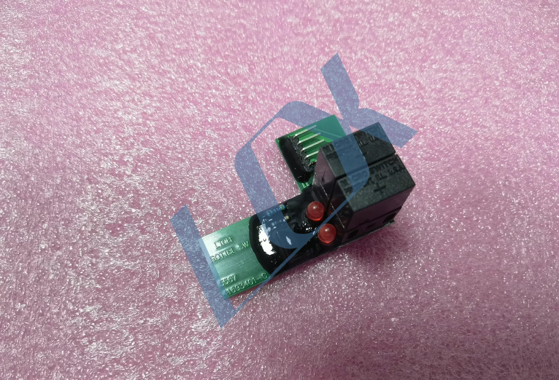
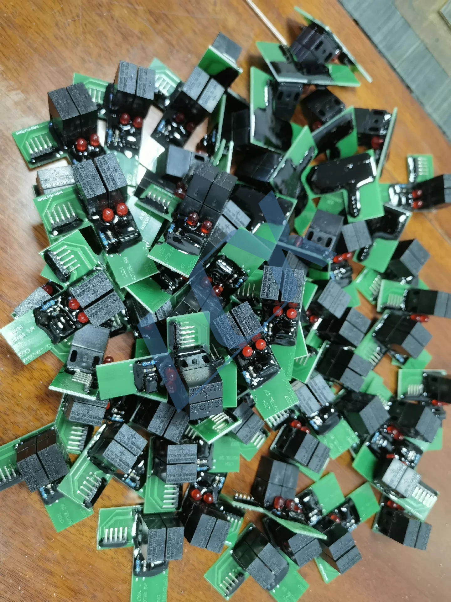
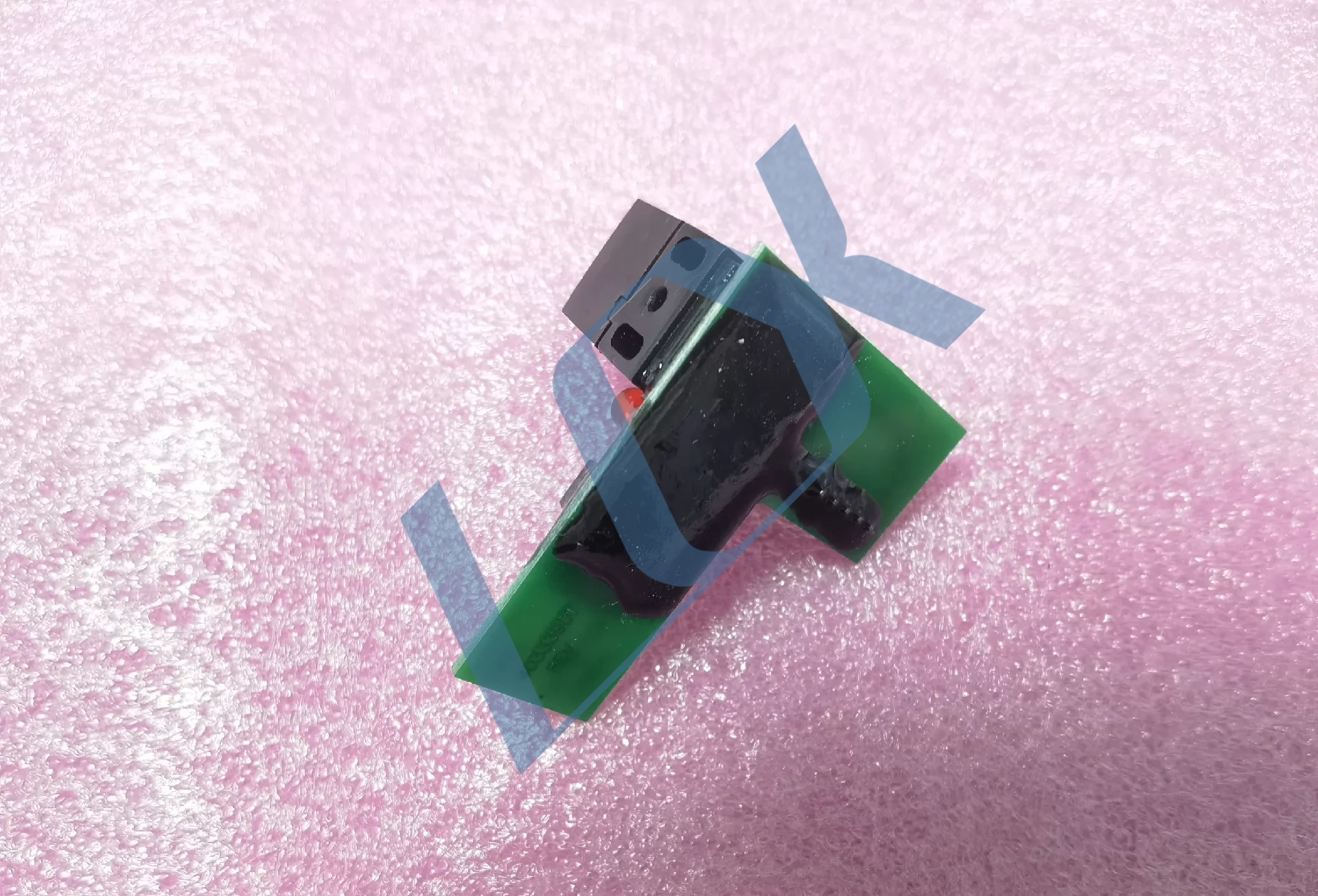
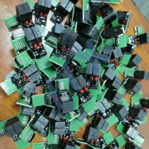
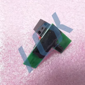
Universal Instruments Component Insertion Machine 41693401 Turntable Board
Complete Compatible Model List
This turntable board is a universal spare part for Universal Instruments single-head axial/radial component insertion machines, covering the following mainstream models:
Series Specific Models Remarks
AI Axial Component Insertion Machine Series 6241, 6241B, 6291, 6380, 6380A, 6380B, 6380E Most common compatible models, including older and improved versions
Radial Component Insertion Machine Series 6360, 6360A, 6360B, 6360E Universal for radial component insertion equipment
High-Speed Single-Head Component Insertion Machine Series 4796, 4797, 4798, 4799, Genesis Single-head models. PCB version needs to be checked for some platforms (41693401-C is the universal version)
⚠️ Additional Notes:
The PCB silkscreen markings on this board… 41693401-C is compatible with all devices labeled with part number 41693401. Different suffixes (e.g., no suffix /-A /-B /-C) represent version iterations; electrical interfaces are completely universal.
This is not applicable to Universal dual-head/multi-head insertion machines (such as Genesis dual-head and Advantis platforms). These models require a dedicated turntable control board.
Share to:
Universal Instruments Rotary Table Switch Board 41693401
Part Number: 41693401 (PCB silkscreen marking 41693401-C, version compatible)
Aliases: Turntable Sensor Control Board / PC BD L RT T SW ASM
Applicable Models: Universal Instruments’ entire series of single-head insertion machines (AI insertion machines), such as axial/radial component insertion machines
Functional Positioning: The turntable position detection and switch control board is the core component of the insertion machine’s turntable positioning system. It is responsible for monitoring the turntable position, controlling the start and stop of movement, and ensuring insertion accuracy and stability.
🛠️ Structure and Function Analysis
Core Components:
Dual Micro Switches (Honeywell microswitches): Used to detect the mechanical position signal of the turntable, realizing closed-loop control of turntable positioning.
Two Red LED Indicator Lights: Used for status feedback, displaying signal trigger or fault status.
Black potting compound protection: Provides moisture, dust, and vibration protection for critical circuits, suitable for harsh operating environments in industrial equipment.
Direct-plug connector interface: Quick-plug design for easy equipment maintenance and replacement.
Key functions: Precisely controls the rotation and positioning of the turntable, ensuring perfect alignment of the insertion head with components and the PCB board.
Real-time monitoring of turntable movement status prevents misalignment, overtravel, and other malfunctions, improving production yield.
Compatible with all Universal single-head insertion machines, a universal spare part for stable equipment operation.
💡 Application and Maintenance Points
Common fault symptoms: Inaccurate turntable positioning, insertion misalignment, equipment error shutdown, often caused by poor switch contact or aging potting compound leading to abnormal signals.
Maintenance recommendations: Regularly clean switch contacts to prevent dust and oil from affecting signal transmission.
Check for cracks in the potting compound; if damaged, reseal to prevent circuit damage from moisture.
Power off the machine before replacement to prevent oxidation or damage to interface pins and ensure stable signal connection.
📦 Additional Notes This model is a universal spare part for Universal Insertion Machines. When purchasing, please check the part number and version (41693401-C is a common version) to ensure full compatibility with the machine model.
(I) Typical Fault Phenomena
Fault Manifestation Directly Related Causes
Turntable positioning misalignment, inaccurate plug-in position
Microswitch contact oxidation/poor contact, cracked and damp potting compound
Equipment reports “Turntable position error” and stops
Switch signal loss, LED indicator light not lit, poor soldering of interface pins
Turntable rotation jamming, unable to return to zero
Switch mechanical jamming, short circuit causing abnormal signal
Intermittent error reporting, temporarily restored after restart
Poor wiring contact, worn switch contacts, aging and insulation failure of potting compound
(II) Step-by-Step Troubleshooting Process (Sorted from easiest to most difficult)
1. Quick Appearance and Basic Inspection (No Disassembly Required)
Step 1: Observe the indicator lights
Under normal conditions, the corresponding LED light should flash once every time the turntable triggers positioning. If the light does not illuminate, prioritize the following troubleshooting steps:
Is the power supply to the device normal? (Check the power module output voltage.)
Is the connector interface loose, or are the pins oxidized/bent?
Step 2: Cleaning and Physical Inspection
Wipe the interface pins with anhydrous alcohol. Check for cracked potting compound, corrosion/burnt marks on the PCB, and physical damage to the microswitch.
2. Circuit and Signal Testing (Basic electrical tools required)
Step 1: Switch Contact Continuity Test
Using a multimeter in continuity mode, manually press the microswitch and measure whether the contacts can conduct/disconnect normally. If the continuity is unstable, it indicates contact wear or oxidation, requiring replacement of the switch or refinishing of the contacts.
Step 2: LED and Circuit Continuity Test
Measure the voltage across the LED (normally around 5V). If the voltage is normal but the light does not illuminate, the LED is damaged; if the voltage is 0, check for open circuits in the PCB circuit and damaged resistors/capacitors.
Step 3: Internal Circuit Inspection of the Encapsulant
If the encapsulant is cracked, causing a short circuit due to moisture, the following steps are necessary:
Use a hot air gun at a low temperature to soften the encapsulant layer and carefully peel off the damaged part.
Clean the damp area with board cleaner and dry the PCB.
Reapply conformal coating or encapsulant to restore insulation protection.
3. Replacement Verification and Fault Location
If the above steps fail to locate the fault, directly replace the known intact 41693401 board and test if the equipment returns to normal. If the fault disappears, the original board is damaged; if the fault persists, upstream components such as the mainboard and turntable mechanical structure need to be checked.
(III) Preventive Maintenance Recommendations
Regular Cleaning: Clean the microswitch contacts and connector interfaces monthly to avoid dust/oil buildup.
Moisture and Vibration Prevention: Avoid prolonged operation of the equipment in high humidity environments. Regularly check the condition of the encapsulant and repair any cracks promptly.
Spare Parts Reserves: It is recommended to keep 1-2 new/refurbished boards on hand to avoid production stoppages due to parts shortages in case of failure. 📋 III. Procurement and Replacement Precautions
Part Number Verification: Ensure the board’s silkscreen markings are 41693401 or 41693401-C, and that the interface pin definitions are fully compatible with the equipment.
Quality Differentiation: New replacement parts and refurbished parts are available on the market. Prioritize new parts with test reports to avoid refurbished parts that may fail again in a short period due to switch wear.
Installation Instructions: Power must be disconnected during replacement. After installation, check the clearance between the board and the turntable’s mechanical structure to prevent improper installation from causing accidental switch triggering.
LCX Copyright © 2026 All Rights Reserved.